


Clamp Force: Why It’s Vital to Your Injection Molding Process and How to Calculate It
By Jim Clifford, Consultant / Trainer, RJG
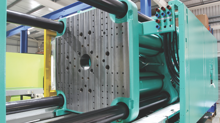
Clamp force is one of the most overlooked portions of the Injection Molding process. I can’t count how many times I’ve walked up to a molding machine to see that the clamp force was set at max. This can cause machine or mold damage if the mold is not properly sized for the machine it is running in.
So, what is clamp force? Why does it matter? And how do you calculate it?
What is Clamp Force?
Available clamp force is the clamp tonnage the machine is capable of. The machine needs to have enough clamp force to hold the mold closed to withstand the plastic pressure that is being developed inside the mold cavities and the cold runner. We generally recommend calculating the clamp force each individual part needs rather than running it at the machine max.
Why Does Clamp Force Matter?
How many parts do you run in your plant where every critical dimension is running right at the mean or the center of the tolerance? In a perfect world, you would say all of them, but we all know this isn’t a perfect world. The majority of the time, there are a few critical dimensions that are in tolerance but close to the high or low end of the limits. If the clamp force is adjusted without being optimized, you may be at risk of throwing some dimensions out of spec. This can be even worse if you are already running under a deviation to your customer.
How would it look if you went back to your customer and said you needed a deviation for an even wider tolerance on a critical dimension? Then the next time it runs, it is started up with the clamp tonnage back at the original setting, but now the dimension has changed. This could get you going down that rabbit hole again.
Here’s an example to show how important clamp force actually is.
I recently ran a sample in our lab, only adjusting one set point. As you can see below in Fig. 1, this changed the peak shot volume, peak cavity psi, pack rate, and cooling rate. It also affected the length, width, and thickness of the parts. What variable could I have possibly adjusted that made the process go sideways?
We should look at this from the plastic’s point of view using the four plastics variables: Heat, Flow, Pressure, and Cooling. Which of these variables would have the most effect on the part dimensions?
Answer: clamp tonnage.
I know, I know… it was a trick question, but it’s so important that it has even been referred to as the fifth variable. Most people wouldn’t even think twice about this adjustment having any effect on part dimensions, but it can completely change what is happening in the cavity. Too often, people make other adjustments to the process to get dimensions back in tolerance without ever considering clamp force.
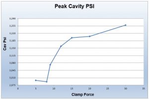
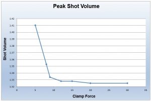
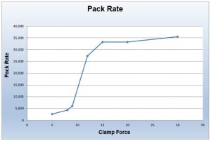
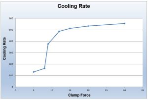
Figure 1
When the clamp force is set too high, it has the potential close to off vents, damage parting lines, crack cavity blocks, and more. I have personally seen molds in the industry that were damaged enough that they were past the point of a simple repair, and some mold components can take weeks to replace. In a world where neither the molder or the customer carries a lot of inventory, it could be catastrophic if you had a high-volume production mold down for weeks waiting on repairs.
One other area to be aware of is if the mold is too small for your machine, and the clamp tonnage is set too high, you can start to warp or bend the platens around the mold base. You may not physically be able to see this warp or bend, but you may notice flash in the center of the mold or other molds that run in this machine. When this damage occurs, it can lead to downtime and scrap, reducing your company’s overall profit.
How Do You Calculate Clamp Force?
First, we need to calculate the total projected area of the part. This is the two-dimensional projected area of all parts and cold runners on the parting line of the mold. You may ask: why would you need to calculate the area of the runner if you are in the business of making good parts not good cold runners? The cold runners still have plastic pressure that is trying to force the mold halves apart.
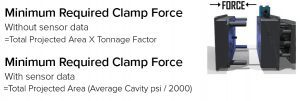
Once you have calculated the projected two-dimensional area of all parts and runner, multiply it by the material supplier’s recommended clamp force—they generally supply this recommended clamp force in tons/in² (see calculation in Fig. 2 below). This calculation will get you in the ballpark for the amount of clamp force needed, but it may not be exact. When material suppliers establish the clamp force requirement, they are not doing it on your exact mold. If you want to get this required clamp force more accurate for your particular part, you can use average cavity psi if your mold is equipped with cavity psi sensors.
For example, let’s use a mold that has a Post Gate pressure of 9,000 ppsi and an End of Cavity pressure of 3,000 ppsi. When we add both of these pressures together and then divide by two, it will give an average cavity pressure of 6,000 ppsi. Since we rate injection molding clamp forces in tons, we will need to divide the 6,000 ppsi by 2000 lb, which gives us 3 tons/in². You can now use this clamp force to multiply by the total projected area to establish the recommended clamp force for your mold. This formula can also be found in Fig. 2 below.
Optimizing by Part Weight
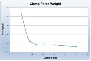
Another method to optimize your clamp tonnage involves adjusting the setting and looking at part weight. Start out running parts that are full and packed out to an acceptable level at a higher clamp tonnage, then reduce clamp tonnage and record the part weight. When you notice the part weight starts to increase, that is the point where the mold halves are starting to separate.
The graph below in Fig. 3 shows an example of a sample I ran with a mold in our lab. You can see from 12 tons up to 30 tons the part weight remained pretty consistent. When the clamp tonnage was set to 10 tons or less, the part weight started to increase. In this scenario, I would set the clamp tonnage at 15 tons so there’s a safety net.
If we had gone by the material supplier’s recommended clamp tonnage of 3 tons/in², we would have run the clamp tonnage at 25 tons. By optimizing the clamp force based off part weight, it allows the mold to vent easier, prevents over clamping, and allows for energy savings.
Clamp Mold Deflection
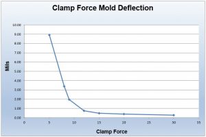
The mold we ran the sample on was also fitted with mold deflection sensors, so we could see how much deflection the mold was seeing at each clamp tonnage. As you can see in Fig. 4, the mold deflection was a direct correlation to the part weight increase at the different clamp tonnage settings.
Having mold deflection sensors in your mold can be very helpful to see if your clamp force has changed or if something is going on with the mold itself. If you have an eDART® with mold deflection sensors in your mold, you could actually save a template and see at a quick glance when the mold deflection has changed. This would point you in the direction of looking at clamp force instead of the other four variables.
Other Measurements
While running the sample, I also decided to take part measurements at all of the clamp force settings. This was a basic rectangle part, so I measured length, width, and thickness. I was surprised to see that all three dimensions shifted at the different clamp settings as well.
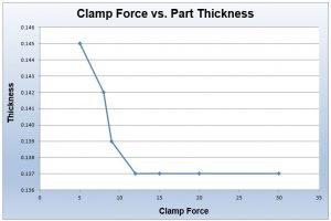
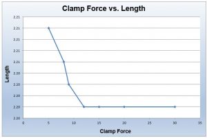
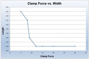
Conclusion
If you have a part that is running at the high or low end of tolerance on critical dimensions, a change to clamp force could throw the dimensions out of tolerance, affect venting, and cause tool wear or damage. So, the next time you see a shift in your process or part dimensions, make sure to look at the four process variables as well as the clamp force before you make changes.