

How to Determine when a RJG Cavity Pressure Sensor requires Calibration
Applies to: RJG Strain Gauge Sensors, RJG Piezo Sensors, Calibration, Repair
Warnings: Please follow your company’s quality policies and procedures when making the determination to calibrate RJG Cavity Pressure Sensors
Description of Problem: A common question we get asked from our clients is “How often do I need to send my sensors back for calibration?” or “How do I know when my sensors need calibration?” This article will discuss some common issues that factor in the decision and describe several strategies you might use to decide when to calibrate sensors
RJG Cavity Pressure Sensors are designed to hold their calibration during their operating life. The vast majority stay within a 2% accuracy specification, which is sufficient for most client applications. RJG’s standard recommendation is that sensors be calibrated every year, but the need for regular calibration depends largely on the accuracy required for your application and their requirements for your quality system and industry regulations.
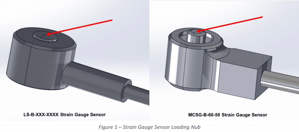
Strain Gauge Sensors & Piezo Sensors – Loading Nub Wear
The most common cause of calibration drift is wearing of the sensor’s loading nub (Figure 1), where the ejector pin contacts the sensor. The wear pattern on the nub changes the way the sensor is loaded, which causes calibration drift.
For Strain Gauge sensors, the best indicator of this type of wear is “Zero Offset Shift” which can be monitored on the eDART® System, CoPilot® System (See Appendix A Below) or the RJG Sensor PreCheck® Hardware. In extreme cases, the sensor’s calibration can shift by as much as 10%, for example if the nub is completely worn flat. However, the vast majority of sensors show a calibration shift of less than 2%, which is within RJG’s repair and recalibration specification.
For Piezo Button Sensors (Piezo 9204, Piezo 9211, & Piezo 9210) nub wear can also cause calibration shift, particularly on the 9211 Piezo Sensors. Like the strain gauge button sensor, most piezo sensors show a calibration shift less than 2%. Note that there is no meaningful zero offset measure for Piezo Sensors, where it is more difficult to determine when a piezo sensor may be out of calibration. Rarely, if a piezo sensor is badly side loaded, or overloaded, the piezo crystal can crack, which can cause the calibration to drop by approximately 20-50%
Piezo Flush Mount Sensors ( Piezo 6159, Piezo 6157 ) are not susceptible to wear, although like piezo buttons the crystal can be cracked, particularly in the rare instance that the sensor tip is bent, or side loaded. As with Piezo buttons, it can be difficult to determine when a sensor may be out of calibration.
Note: Thermocouple Temperature Sensors do not require calibration
Common Factors Affecting the Need for Sensor Re-calibration
How much Accuracy is Needed for a Client’s Application?
Some applications require more accuracy than others. If you are using cavity pressure control on a precise part with a narrow processing window, it may be important to maintain the sensor calibration to within 1%. If you simply detecting short shots, you may be able to tolerate calibration shifts of 5% or more. As a point of reference, a 2% calibration error means that a cavity pressure of 3000 psi may read as low as 2,940 psi, or as high as 3,060 psi, which is barely noticeable in most applications. For most applications, calibration accuracy of 2% is more than sufficient, which is why RJG uses this as our specification for repaired sensors.
What Quality System Regulations Must the Client Meet?
If a client must comply with FDA quality system requirements, or those of other stringent quality systems, sensor calibration may be required. However, even in these cases, the client often has flexibility to adjust guidelines to meet the needs of their application. This article will discuss different calibration strategies below.
How Many Cycles has the Sensor Been Exposed To?
In the most aggressive environments, it takes at least 100,000 cycles for a sensor to show significant calibration errors/shifts. In more typical applications, the calibration will remain stable for 500,000 – 1,000,000 cycles. Even then, RJG has many sensors in the field with multiple millions of cycles that show little calibration shift. If a sensor is in a low volume mold that sees fewer cycles, the need for recalibration is minimized.
How Much Load do the Sensors See?
The higher the peak load on the sensor, the more the loading nub can wear, and the higher the potential for calibration shift. Because of this, low force applications show less calibration shift than high force sensors, and sensors that run at the lower end of their force range (e.g. Less than 40% full scale) show less calibration shift than sensors that run at the high end of their range
What Temperatures are the Sensors Operating at?
The higher the mold temperature, the greater the potential for calibration shift. Below 100 °C, calibration usually remains quite stable. Sensors running at 150 – 200 °C have a greater potential for permanent calibration shift over time.
How Much Visible Wear Can Be Observed on the Sensors Loading Nub?
It is normal for the loading nub to show some wear. However, if the wear pattern exceeds half the diameter of the loading nub, the sensor calibration is more likely to have shifted significantly.
How Much Zero Offset Shift does the Sensor Show in the Raw Data Viewer or on the Sensor PreCheck?
For strain gauge sensors, the zero offset is the reading of the sensor with no load applied. While not directly related to the sensor calibration, the zero offset does provide indication that the sensor’s calibration may be suspect. Note: Zero Offset does not apply to Piezo Sensors. Instructions for finding the Zero Offset are provided in Appendix A Below.
Is a Sensor Reading Abnormally High or Low Relative to it’s Template or to Other Sensors?
Sometimes this can be an indication of a calibration shift, but before sending sensors in for repair, check for other more common causes of erroneous readings. Are the sensor pocket dimensions correct? Is the sensor being Preloaded? Is there contamination in the sensor pocket? Is the Ejector Pin binding, due to misalignment, debris/contamination, or galling? Check these first before sensing your sensor in for recalibration.
Common Re-calibration Strategies used by RJG Clients
Over the years, we’ve seen clients use a variety of strategies to decide when to re-calibrate their sensors.
Calibrate Annually:
For applications with the most stringent calibration requirements, annual recalibration may be required. Sensors can be returned to RJG for recalibration. Note that only a small number of our clients send all their sensors back for annual calibration. To request an RMA to start the recalibration process, click here.
Perform Risk Assessment:
Some clients will use a risk assessment to identify which sensors should be returned for regular calibration. Risk factors may include the stringency of a part’s quality requirements, the number of cycles put on the sensor each year, or any other factors mentioned above.
Build History to Show Calibration Stability:
Several clients have build a recalibration history and have found over time which applications show calibration shift and which do not. If you are routinely sending sensors back for recalibration and they are always with specification, this provides good data to tell you that routine recalibration may not be required.
Re-calibrate Sensors Based on a Zero Offset Shift (Strain Guage Only):
For strain gauge sensors, thee zero offset is the reading of the sensor with no load applied. Appendix A explains how to find the zero offset for your strain gauge sensor. Some clients will monitor the sensor zero offset during routine maintenance and will send sensors back if the offset exceeds a certain value
Re-calibrate Sensors When Data is in Question:
While RJG does not necessarily recommend this as a primary calibration strategy, it is commonly used when problems arise or when data is in question. As mentioned earlier, there are many reasons that a sensor may read incorrectly, so we recommend that these potential root causes be investigated first before sensing your sensor in for Re-calibration.
A Special Note about Piezoelectric Sensors
Most piezoelectric sensors have a detachable cable, which can be replaced in the field if the sensor needs to be repaired or if the cable length needs to be adjusted. It is important to note the calibration of piezo sensors is NOT influenced by the cable length. If you change the length or replace a cable in the field, the sensor’s calibration remains unchanged.
Also, for analog piezo sensors, (Piezo Sensors Utilizing an LP/LX1-M), each sensor has a unique sensitivity that is reported on the calibration certificate. This sensitivity can be entered into the eDART in Sensor Locations for each sensor. The software provides a default sensitivity for each sensor into the software. Note that this does NOT apply to sensors sold with a mated pair (e.g. those attached to lynx cases with model numbers beginning in LP-B or LP-F – Modules that are obsolete or no longer sold by RJG Inc.)
Appendix A: Measuring a Strain Gauge Sensor’s Zero Offset
For strain gauge sensors, the zero offset is the reading of the sensor with no load applied. If this value shifts by more than 5%, the client may want to consider having the sensor’s calibration checked.
Note that when the sensor is installed in a mold, the zero offset can also be influenced by the installation (e.g. side loading or preloading of the sensor). If the zero offset measurement indicates a potential problem when the sensor is installed in a the mold, it should be measured again outside of the mold as a confirmation.
There are several different ways to measure the zero offset:
The Sensor PreCheck™ is a portable testing device for testing RJG Sensors. Multiple sensors can be tested at one time, and the results are reported in a simple, color-coded format. Must customers return a sensor for recalibration if the “Zero Shift” reads red, although a yellow reading may warrant recalibration in critical applications.
The eDART Software can also be used to measure the zero offset for eDART software versions prior to version 10, the zero offset can be read in pounds in the Sensor Locations page. This must be converted to a percentage of full-scale, dividing by the full-scale load of the sensor (which ranges from 50 to 4000lb depending on the model). The same criteria can be applied as mentioned above for the Sensor PreCheck.
For example, in the screenshot below, a LS-B-127-2000 sensor has a zero offset of 25lbs. The zero offset percentage is 25 ÷ 2000 × 100 = 1.25%. Since this is well below the 5% threshold, it is less likely that this sensor might require recalibration

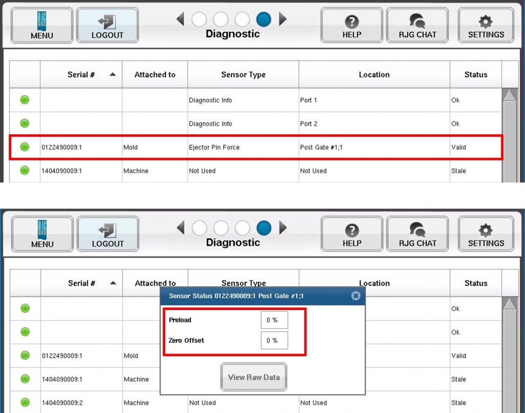
In eDART Version 10, the Diagnostics page provides a color-coded diagnostics for each sensor. By clicking on a sensor, a detail page will appear listing the zero offset, including the zero offset value and the color code Yellow for Warning, Red for Alert.
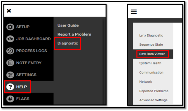
For CoPilot® Systems, the zero offset can be calculated from data found in the Raw Data Viewer, which can be opened from the main menu by selecting « Help » then Diagnostic, then Raw Data Viewer.
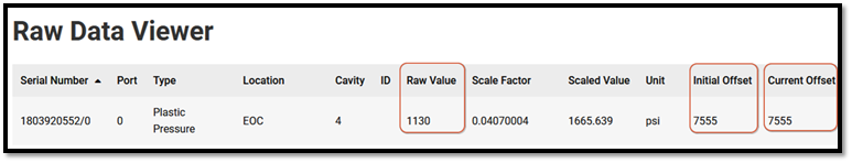
Once a job has been started on the CoPilot System, the Raw Data Viewer screen will display data for each sensor. In the example below, only one sensor is shown.
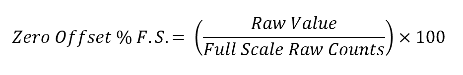
If the press has not cycled, or the mold is on a bench, use the following calculation:
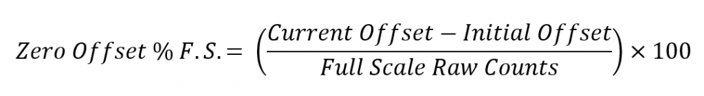
If the press is already cycling, use this calculation:
For example, in the screen below, the press has not yet begun cycling. We can verify this because the Initial Offset and Current Offset are the same.
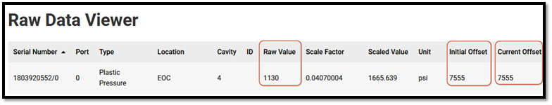
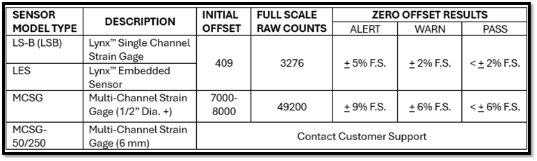
We can also tell that the sensor is an MCSG (Multi-Channel Strain Gauge) because the Initial Offset is between 7000 & 8000. From the table above, the Full-Scale Counts are 49200, and the zero offset is calculated as:
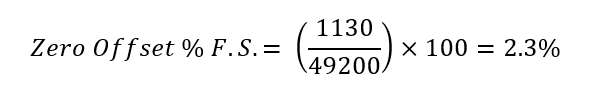
Since this is less than 6%, the sensor passes the zero-offset test.
In the next example, we are using the same sensor, but the press has begun cycling since the job started. We can verify this because the Initial Offset is different from the Current Offset.
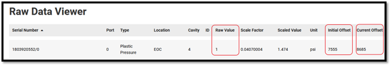
Again, the sensor is an MCSG (Multi-Channel Strain Guage) because the Initial Offset is between 7000 and 8000. From the table above, the Full-Scale Raw Counts are 49200, and the zero offset is calculated as:
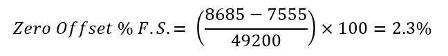
The zero offset is the same as was calculated before the press began cycling, and since this is less than 6%, the sensor passes the zero-offset test.
For any questions, please contact the RJG Technical Support Team
231-947-3111
support@rjginc.com